In Part 1, we established a “digital wire” by connecting the ADC directly to the DAC. Now, we’re ready to add some digital signal processing (DSP). Our first goal is a simple one: A Digital Echo.
This seems straightforward—store the audio, wait a bit, and play it back mixed with the original input. However, as we found out, doing this in pure Verilog on an FPGA involves tackling memory inference, timing constraints, and digital gain staging.
1. The Architecture: Memory as a Delay Line
To create an echo, we need to delay the audio signal. On an FPGA, the most efficient place to store this data is inside the Block RAM (BRAM) slices.
We treat the BRAM as a Circular Buffer. We have a write pointer that increments every sample. We write the current input to RAM[ptr]. To get a delay, we simply read from the same RAM[ptr] before we overwrite it. In a circular buffer, the value at ptr was written N samples ago, where N is the total size of the buffer.
Design Choice: We utilized 32,768 samples of 24-bit audio. At our sample rate of ~38kHz, this provides approximately 0.85 seconds of delays—perfect for a “Grand Canyon” style echo.
2. The Challenge: Block RAM Inference
My initial attempt to write the BRAM logic failed synthesis. Why? Because I tried to use an asynchronous reset (to clear the memory on button press) and read/write in the same cycle without strict timing control. The Artix-7 BRAM blocks are strictly synchronous components.
The Fix: A State Machine. Instead of trying to do everything in one complex always block, I broke the process down into a Finite State Machine (FSM).
localparam S_IDLE = 0, S_READ = 1, S_CALC = 2;
    case(state)
        S_IDLE: begin
            // Wait for new sample trigger from ADC
            if (sample_trig) begin
                mem_addr <= ptr; // Set address
                state <= S_READ;
            end
        end
        S_READ: begin
            // Wait 1 cycle for BRAM read latency.
            // ram_out will be valid NEXT cycle.
            state <= S_CALC;
        end

        S_CALC: begin
            // 1. Calculate Echo Mix
            // 2. Write new data back to RAM
            // 3. Update Output
            state <= S_IDLE;
        end
    endcase
This strict sequencing ensures the synthesis tool (Vivado) recognizes exactly what we want: a Read-First Block RAM.
3. The “Overdrive” Accident (Gain Staging)
Once the memory was working, I implemented the mixing logic: Output = Input + Delayed_Sample
When I tested this, it sounded like a heavy metal guitar distortion pedal. Why? Digital Clipping. Our audio is 24-bit signed integer. If the Input is loud (near maximum value) and we add the Echo (also near maximum), the result exceeds the maximum possible 24-bit value, causing it to “wrap around” or clip hard.
The Solution: Safe Mixing To guarantee we never clip, we use a simple rule: if you add two signals, divide them both by 2 first. In digital logic, dividing by 2 is just a bit-shift right (>>> 1).
// Safe Mixing
    // Input * 0.5 + Feedback * 0.5
    // The sum can never exceed 1.0 (Full Scale)

    mix_temp = (din >>> 1) + (ram_out >>> 1);

    dout <= mix_temp;
This fixed the distortion completely, resulting in a clean, pristine digital echo.
4. The Modular Processor
To manage this new effect, I introduced an audio_processor.v module. Think of this as our “Effects Rack”. It takes the raw input, looks at the switches on the board, and routes the audio through the active effects.
wire signed [23:0] echo_out;

        effect_echo u_echo (
        .clk(clk),
        .rst_n(rst_n),
        .en(sw[0]),           // Switch 0 Control
        .din(l_in),
        .dout(echo_out)
    );

    // Output Routing
    assign l_out = echo_out;  // Send to Left DAC
    assign r_out = echo_out;  // Send to Right DAC
Summary
We now have a working FPGA Audio Processor!
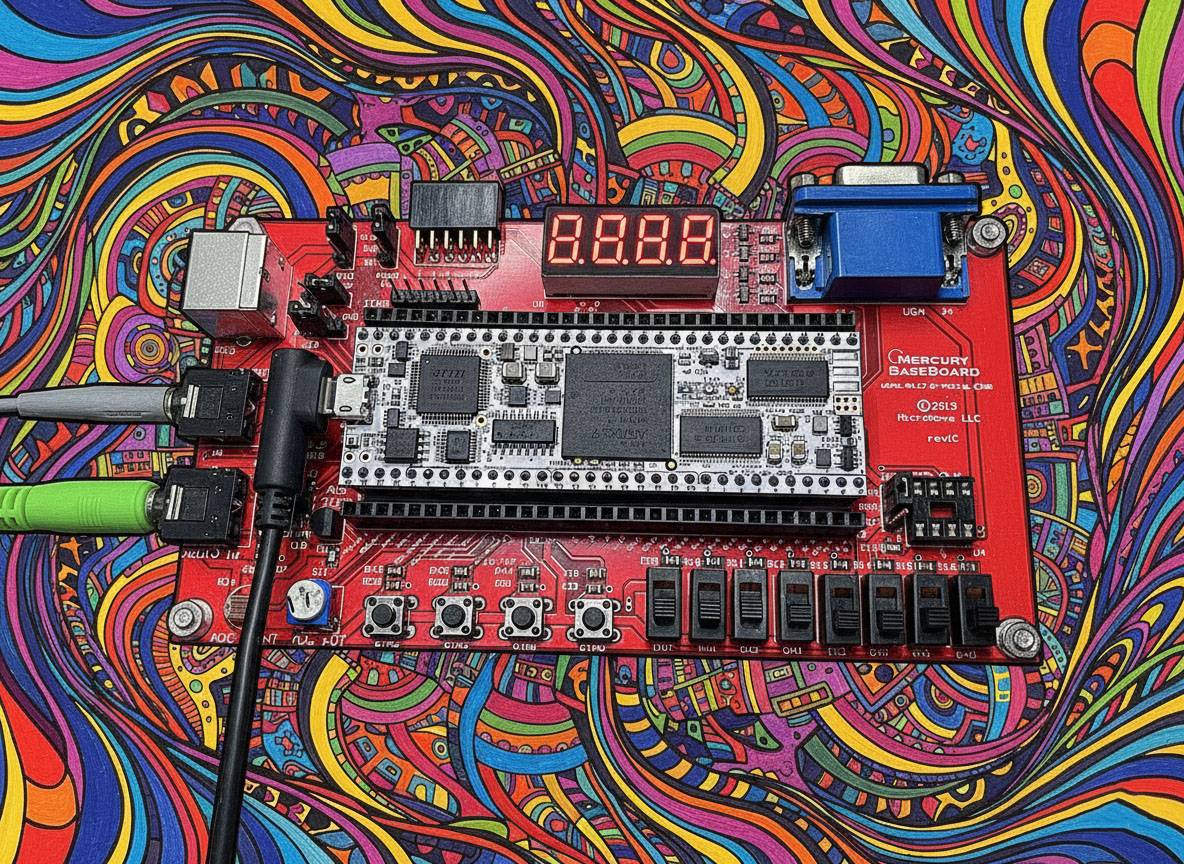
- Hardware: Mercury 2 (Artix-7) with discrete ADC/DAC.
- Logic: Verilog FSM-based BRAM Controller.
- Effect: 0.85s Delay with 50% Feedback.
- Status: Working and Clean.


One thought on “Project Skyverb Part 2: Implementing the Basic Echo”