The Hardware Platform: Mercury 2
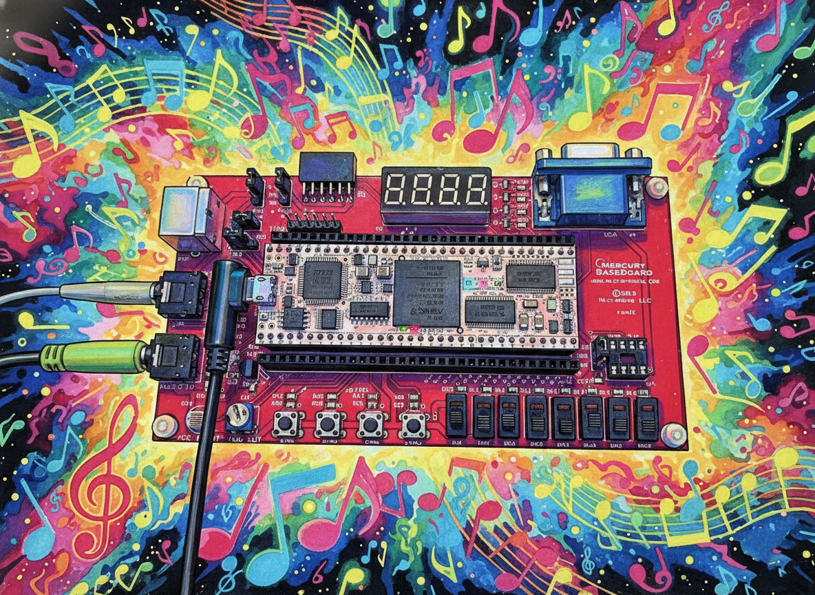
Our brain for this project is the Mercury 2, a development board powered by the Xilinx Artix-7 FPGA (XC7A35T). Unlike many “SoC” boards that come with Linux and pre-configured audio drivers, the Mercury 2 is bare-metal silicon. It gives us a 50MHz clock and a lot of pins. Everything else is up to us.
We are using the Mercury 2 Baseboard, which provides two critical components for audio:
- Input: An MCP3008 Analog-to-Digital Converter (ADC).
- Output: A passive Low-Pass Filter for Delta-Sigma conversion.
Step 1: The Input (Bit-Banging SPI)
The input jack connects to the MCP3008, a 10-bit ADC. To get audio from it, the FPGA acts as an SPI Master.
We didn’t use a library for this. We wrote a state machine in Verilog that:
- Pulls the Chip Select (
CS_n) low to wake up the ADC. - Sends a specific binary command (Start Bit, Single-Ended Mode, Channel 0) via the
MOSIline. - Simultaneously listens to the
MISOline to capture the 10 bits of audio data.
The Challenge: Synchronization. At one point during development, we had clean audio on the oscilloscope but “static” in the speakers. It turned out our SPI clock was misaligned by a single clock cycle, causing us to read the data bits while they were changing rather than when they were stable. A quick adjustment to the state machine fixed the timing, turning the static back into music.
Step 2: The Output (Delta-Sigma Modulation)
Getting sound out is even more interesting. The baseboard doesn’t have a dedicated DAC chip. Instead, we use the FPGA itself to create one.
We implemented a Delta-Sigma Modulator—a clever piece of logic that takes our 24-bit digital audio and converts it into a high-speed (50MHz) stream of 1s and 0s. The density of the 1s represents the voltage.
- Lots of 1s = High Voltage.
- Lots of 0s = Low Voltage.
When this 1-bit stream hits the analog Low-Pass Filter on the board, the jagged pulses are smoothed out into a continuous analog waveform. It’s a “hack” that became an industry standard because it sounds surprisingly good.
The Result: Loopback
By connecting our custom SPI Input driver to our Delta-Sigma Output driver, we created a “Digital Wire.” Sound comes in, gets converted to numbers, travels through the FPGA logic, gets converted back to voltage, and leaves.
When we plug a synthesizer into the Input and headphones into the Output, we hear… exactly what we played. Transparent, latency-free audio.
What’s Next?
Now that we have a working Digital Wire, the fun begins. In Part 2, we will cut this wire and insert our own custom DSP logic: the Strymon Bluesky Reverb algorithm. We’ll be translating floating-point math into hardware logic to create those lush, cloud-like shimmers.
Stay tuned.

One thought on “Project Skyverb Part 1: Building the Digital Wire”