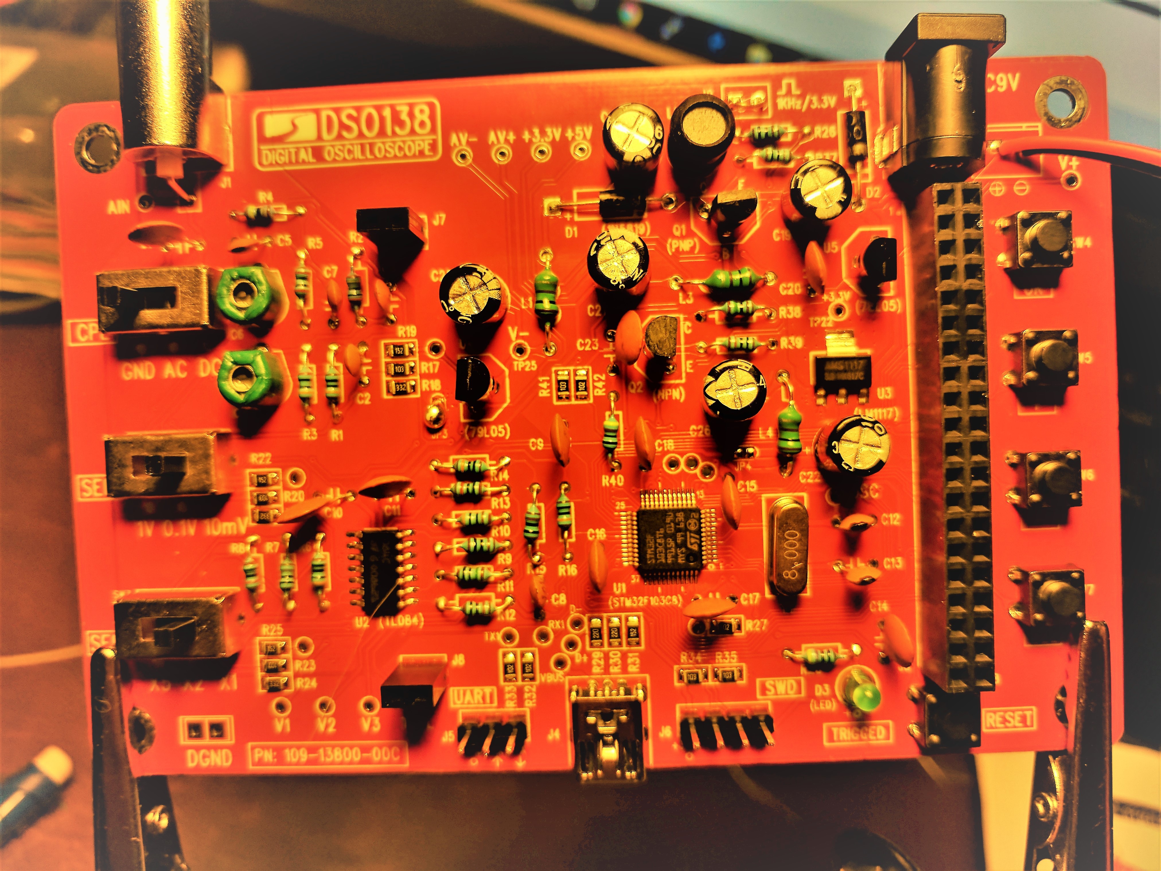
I recently ordered the brilliant Open-source DSO138 oscilloscope
kit by JYE
Tech.
It costs about $20 and is eligible for Amazon Prime shipping, so I thought I’d
give it a try.
It sat in a pile of other electronic parts for the past few weeks while I
waited on a new soldering iron kit and some other parts that I wanted to have
on hand for the build.
I bought mine from Amazon. Be careful which supplier you order from as there
are some counterfeit kits claiming to be from JYE Tech. Even though the design
is open source, JYE Tech has a specific board layout that has been copied part
for part with a few minor modifications and sold as a JYE Tech kit.
JYE Tech DSO138 Oscilloscope (on Amazon) Note: There
are two versions of the kit, one that requires that you solder on the SMD
resistors (13804K) and one with the SMDs already installed (13803K) so that
only the through-hole components need to be soldered into place.
Since we’re moving to a new house (we have to be out of our rental house by
next weekend), I haven’t been spending as much time on my electronics
projects. I got the urge to work on it last night and started around 6 or 7. I
worked on it until about 2:15 when I finally got so tired that I burned myself
(twice) with the soldering iron.
Here is my experience building the kit. It should be noted that I am a very
early beginner hobbyist with electronics, so my soldering skills are terrible.
I got better at it as the night went on, but I think I used my desoldering
tool about as much as I used the soldering iron.
I started by organizing all of the components based on their type.
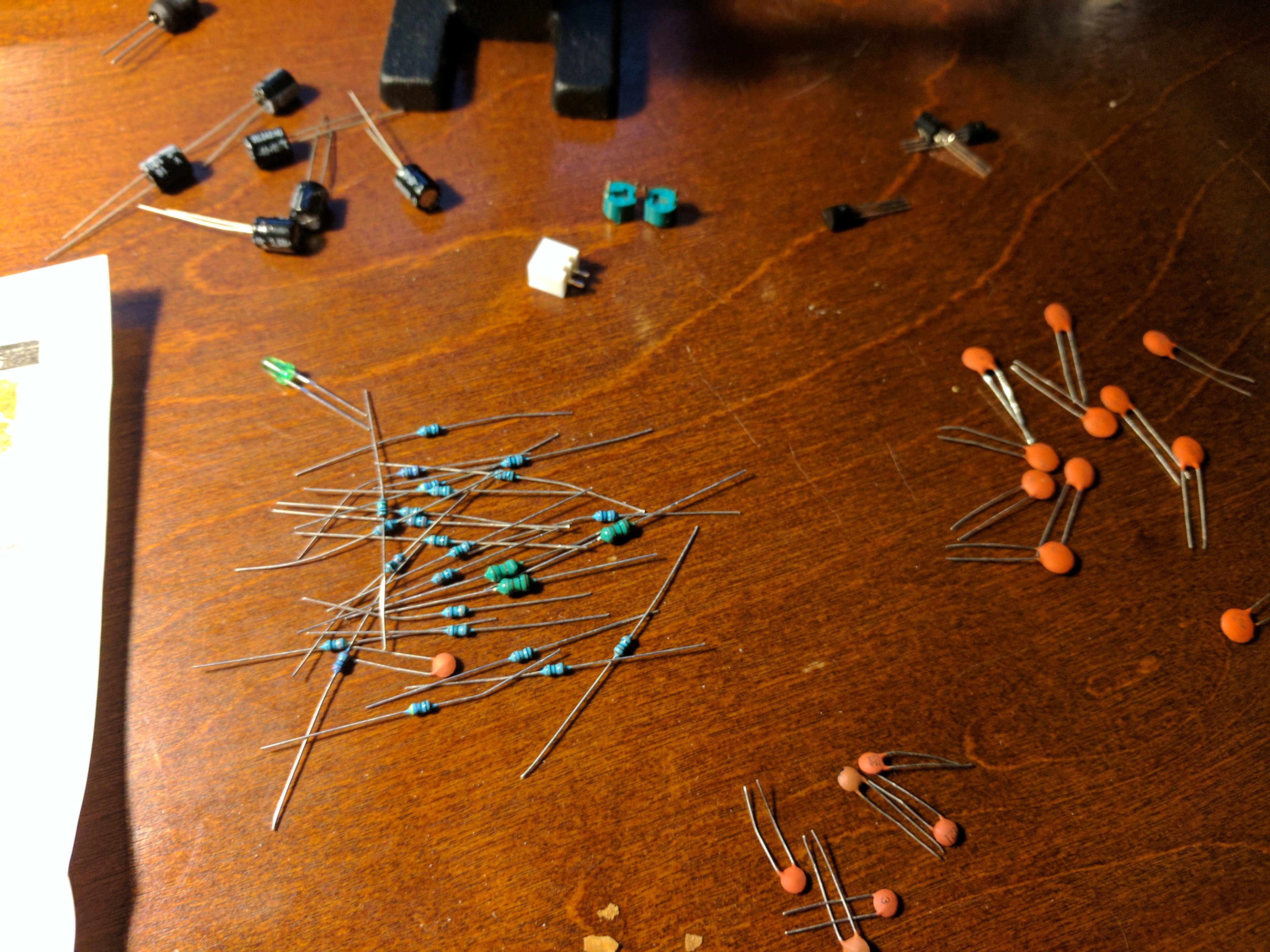
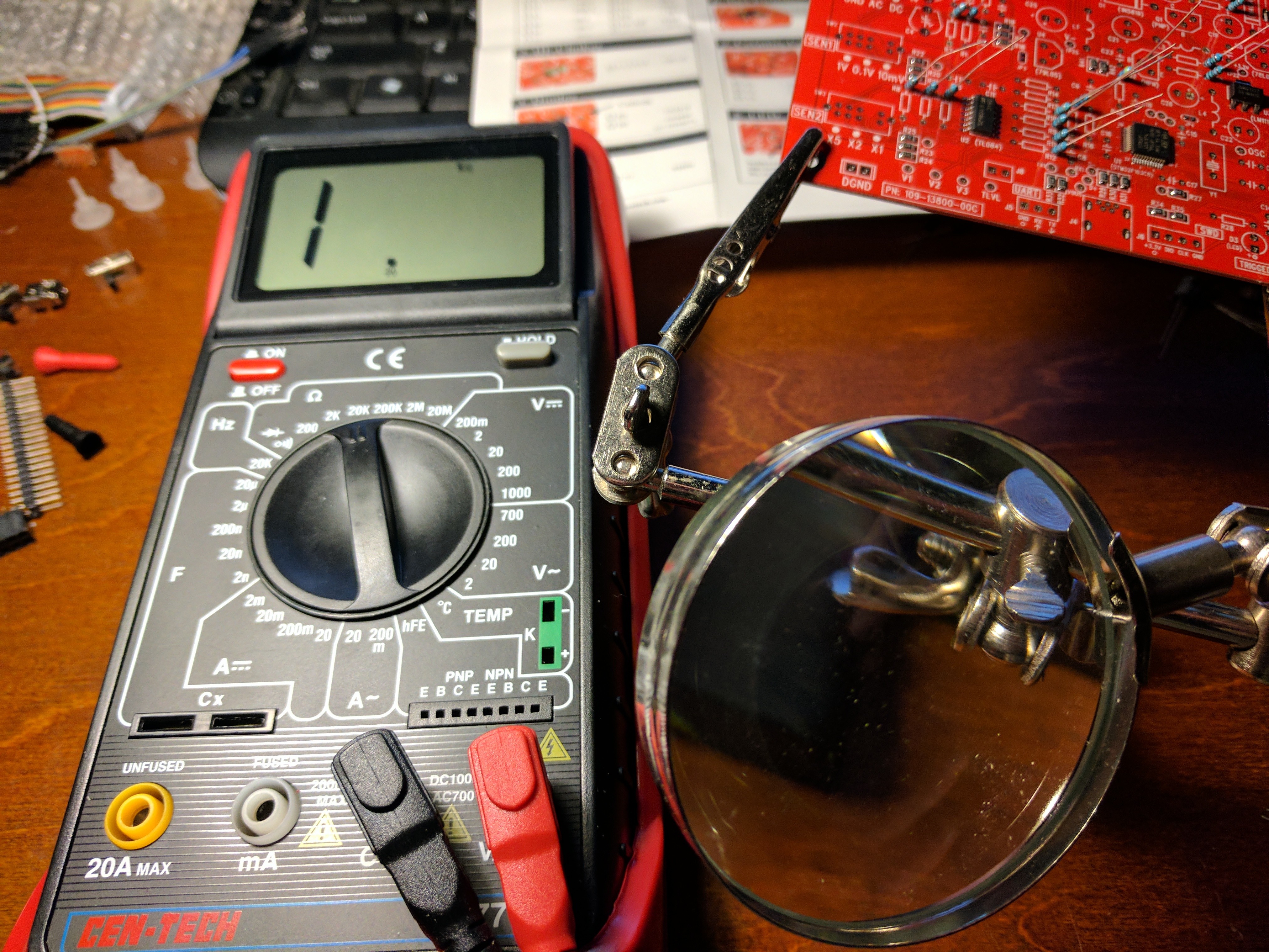
Rather than read the color codes on the resistors, I used my multi-meter to
measure the resistance and then dropped one end of the resistor into one of
the holes on the board. This made placing the components easy. This was also
helpful for the few times that I incorrectly read the values of the
components. There were a few instances where I went to place the component and
there was already one in the hole. In those cases, I re-measured both
components to determine the correct one for the position.
There were two resistors that were of a very high value that I had trouble
measuring. They were valued at 2MΩ and 1.8MΩ. I went ahead and placed them the
best I could. I would later regret this decision, but I’ll cover that later.
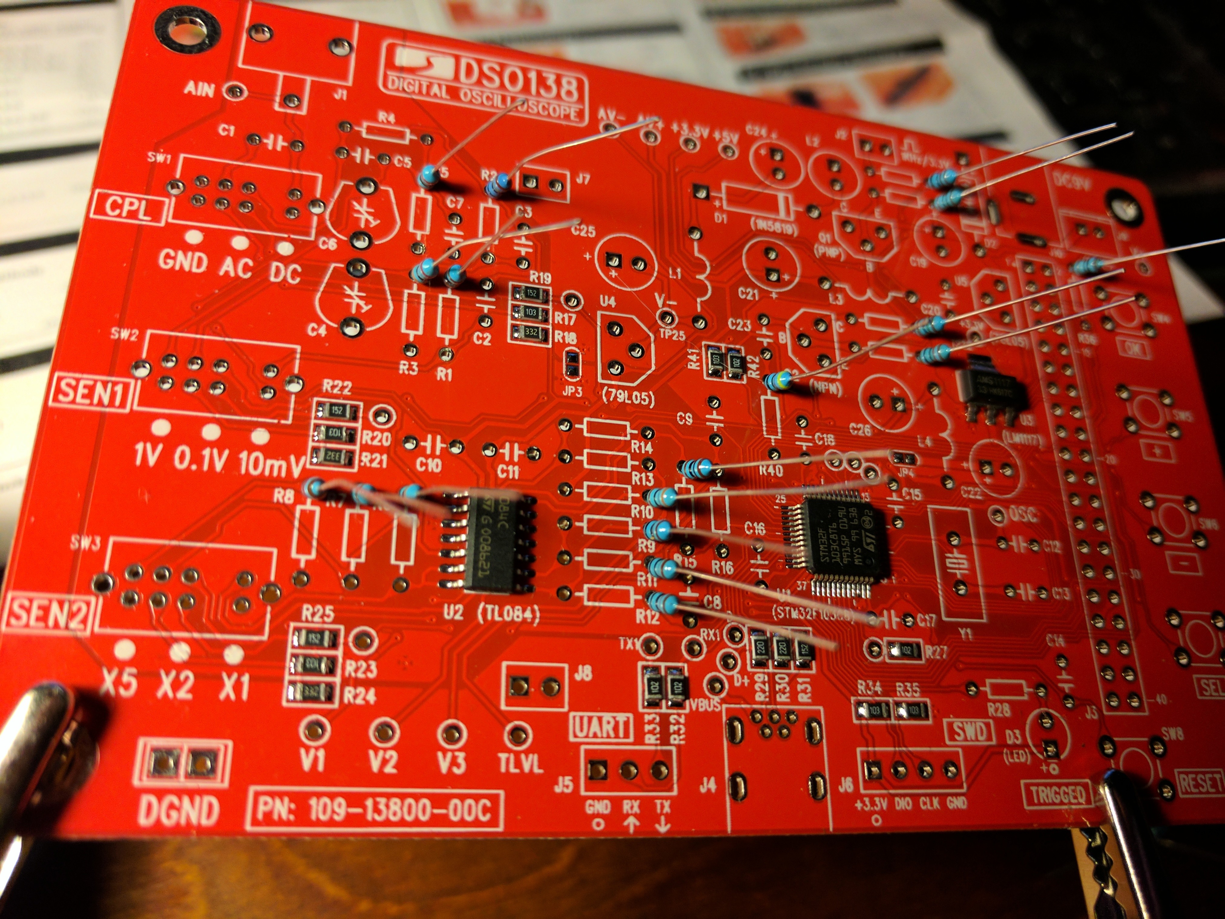
After I had all of the resistors in place, I turned the board over and
soldered them into place.
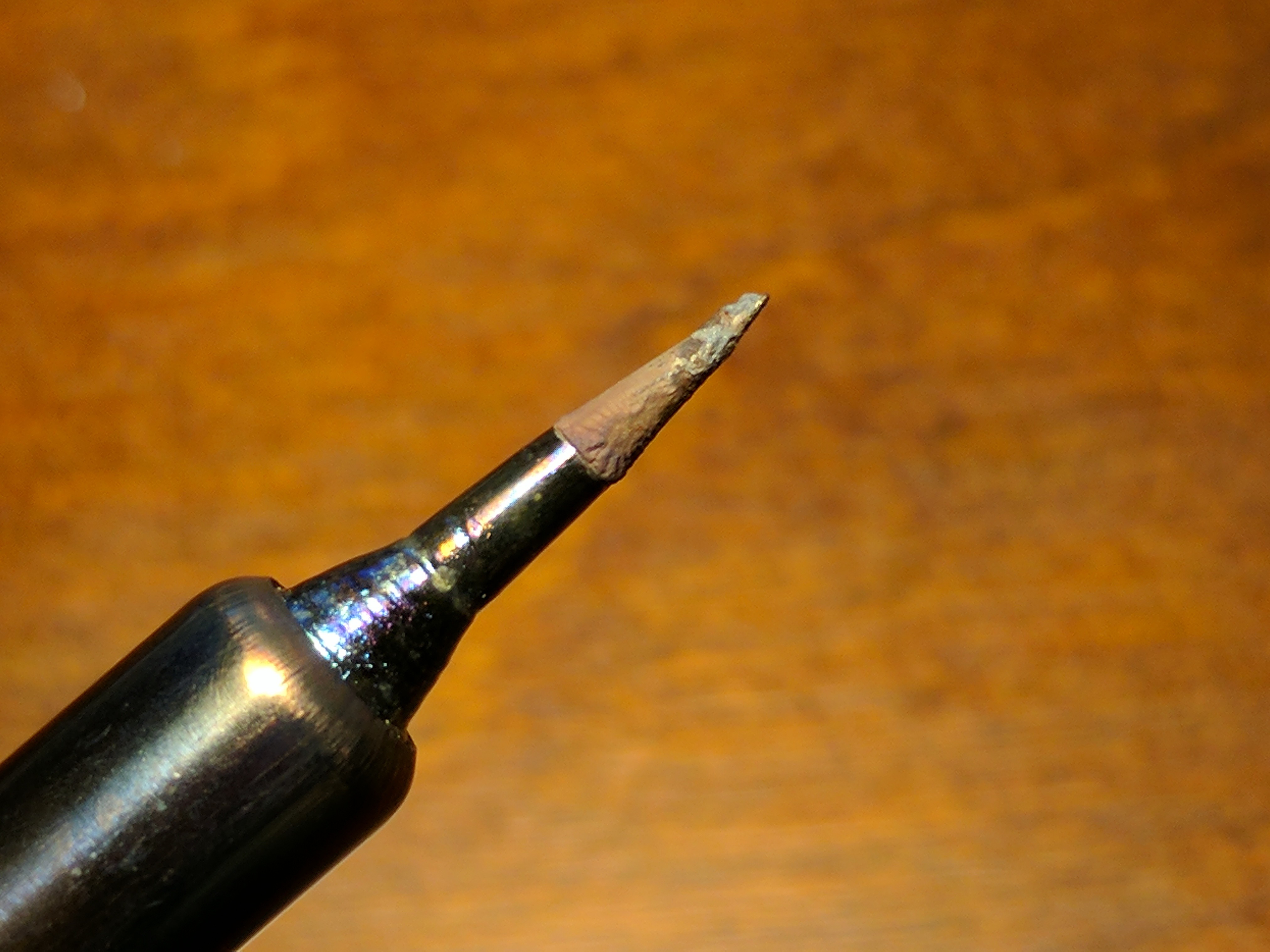
I had a lot of trouble soldering the parts. I decided to switch my soldering
tip to a sharp point. I was using a chiseled edge tip, but it was retaining
solder. I think it’s a combination of the tip, the unleaded solder, and my
fear of burning the board (which kept me from properly heating up the
components to take the solder).
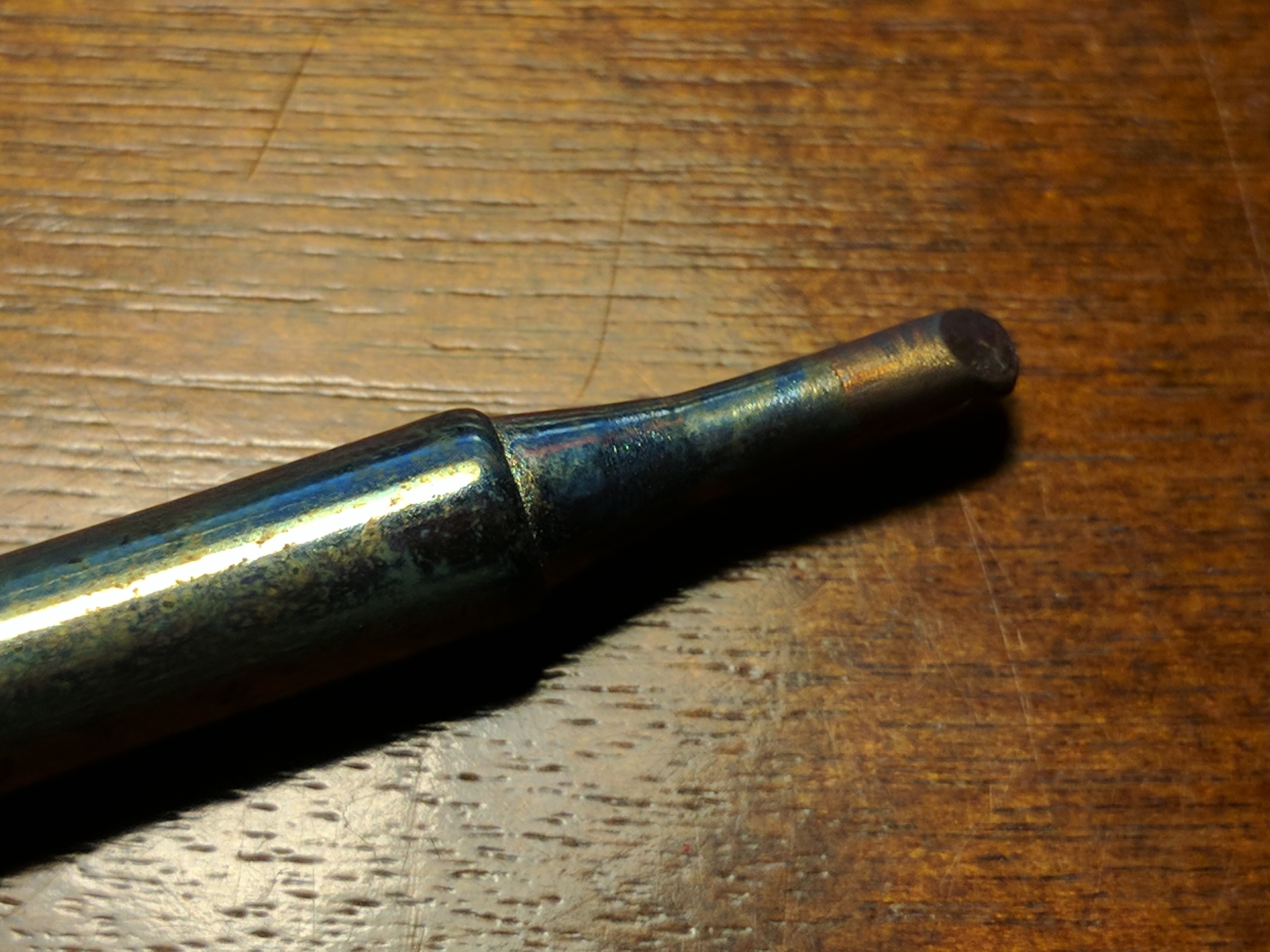
The original tip I was using. I had trouble with this.
You can see how it was already dirty from the soldering work I had done. I
eventually got in a groove and started doing better with my soldering, but not
before a lot of rework.
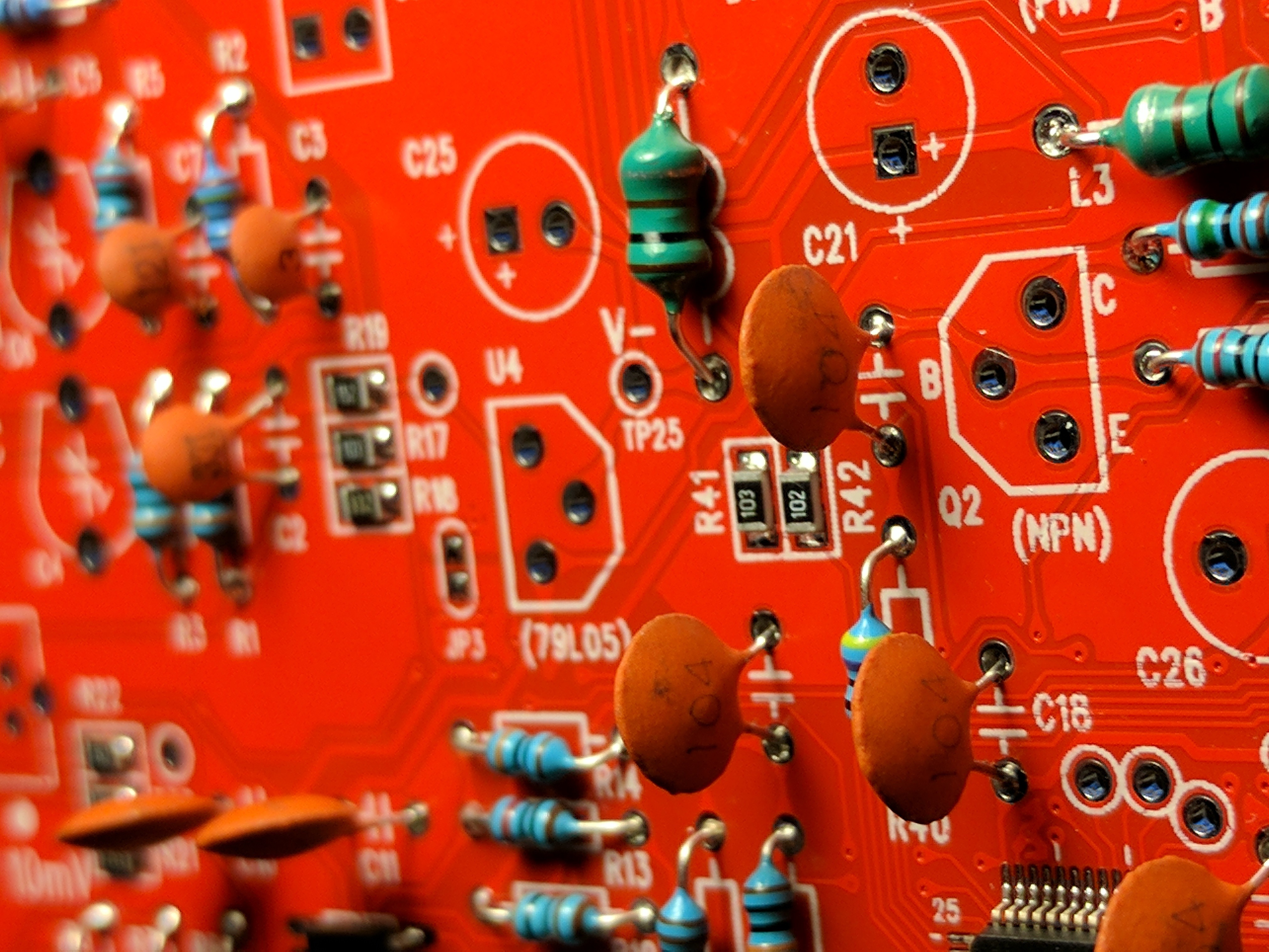
I placed the ceramic disk capacitors next the same way I placed the resistors.

Once they were in place, I soldered them in.
Here is a picture of the completed bottom board.
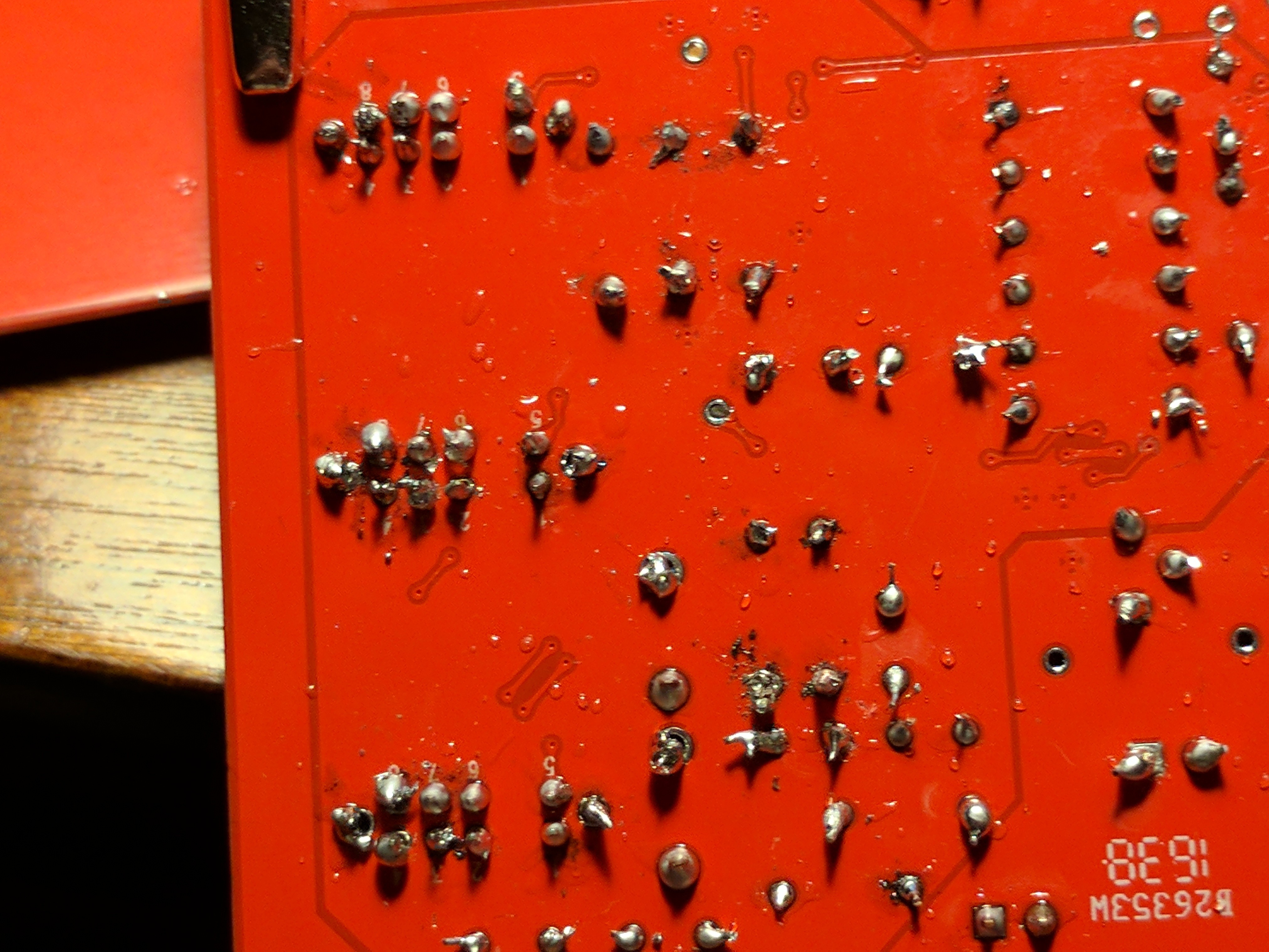
I had a terrible time soldering the three switches. I kept having to solder
and re-solder because the leads were so close together.
Here is a picture illustrating the horrible job that I did. I actually had to
rework some of the switches two or three more times after I took this picture.
You can also see some incomplete solder joints to the right.
I then got to work on the LCD panel. I had to solder on the male header pins
(I had just finished the 40-pin female connector on the main board).
Here is the front side of the LCD panel (where the soldering had to be
performed).
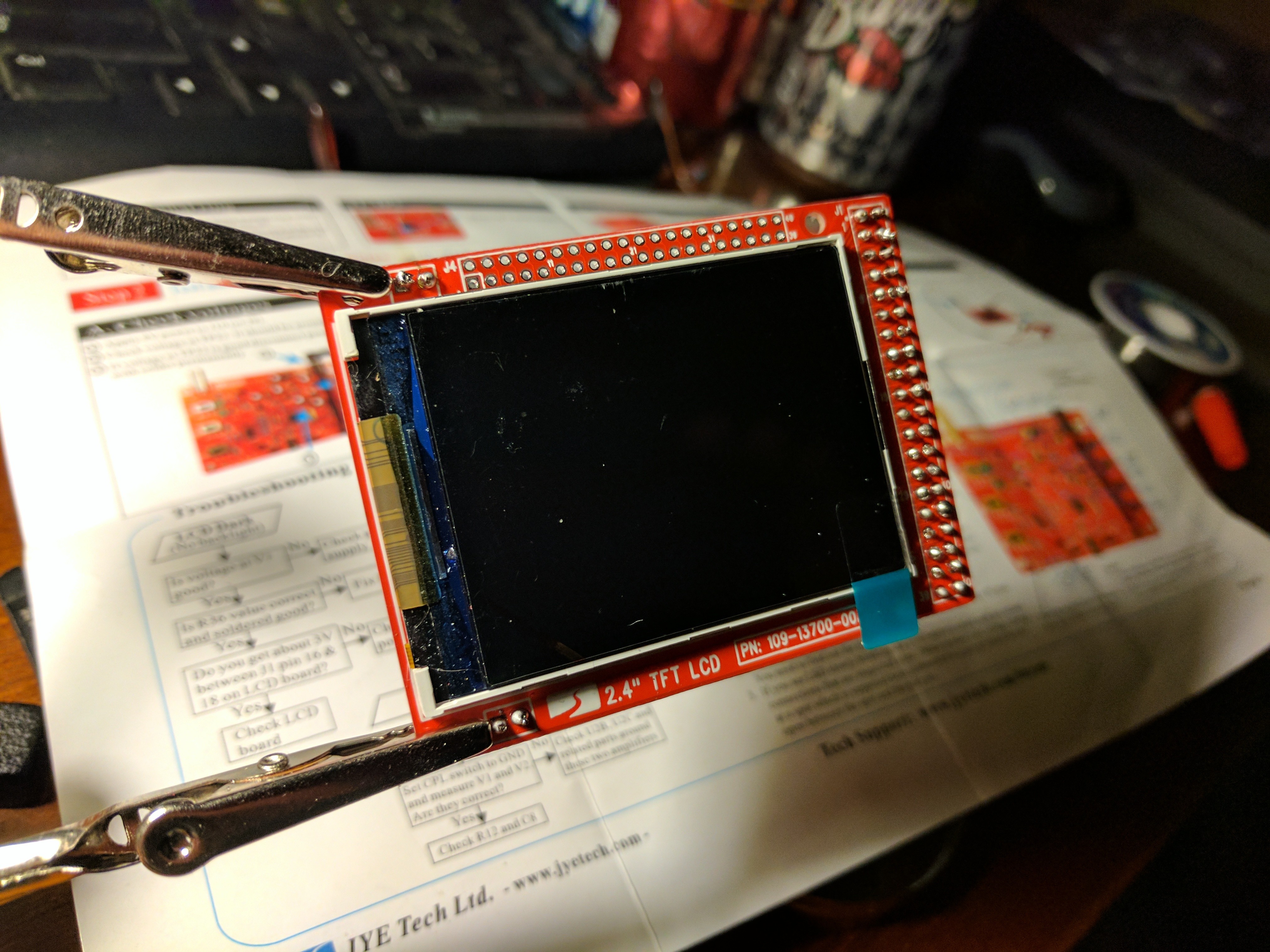
After I got the screen completed, I plugged it all in and attempted to start
it up. I was disappointed when I was greeted with a white LCD screen that had
a fluctuating brightness. I was so distracted by it that I forgot to take a
picture. It’s easy to describe: a blank white screen.
I read in the support forums that if the LED on the scope blinks twice at
startup, then your main board is working. I was happy to see that my scope’s
LED blinked twice at startup. That meant my problem was in the communication
between the board and the LCD.
I spent the next few hours troubleshooting all of my connections. The scope
has a test mode that toggles all of its interface pins from 0 to ~3.3v. This
allows you to run a voltmeter over the pin test points and see if they are
doing what they’re supposed to do. The scope comes with a full schematic
diagram, so I was able to refer to that to see where I needed to put my scope.
At first, I used the test mode to try to isolate incorrectly attached pins
(you can see the test leads above the LCD screen on the LCD panel. Each one of
those holes represents the same number attached to the main board. If you get
a signal from the test lead, then the signal is coming from the main board
into the LCD board).
I quickly realized that I had deeper work to do, so I went to bed frustrated.
I woke up this morning ready to do more troubleshooting.
I decided to go deeper into my troubleshooting and use the continuity tester
on my meter to test each individual pin on the LCD screen to make sure it was,
in fact, connected to the main board. I found two or three pins that were not
connected, so I decided to rework the soldering job on the LCD header.
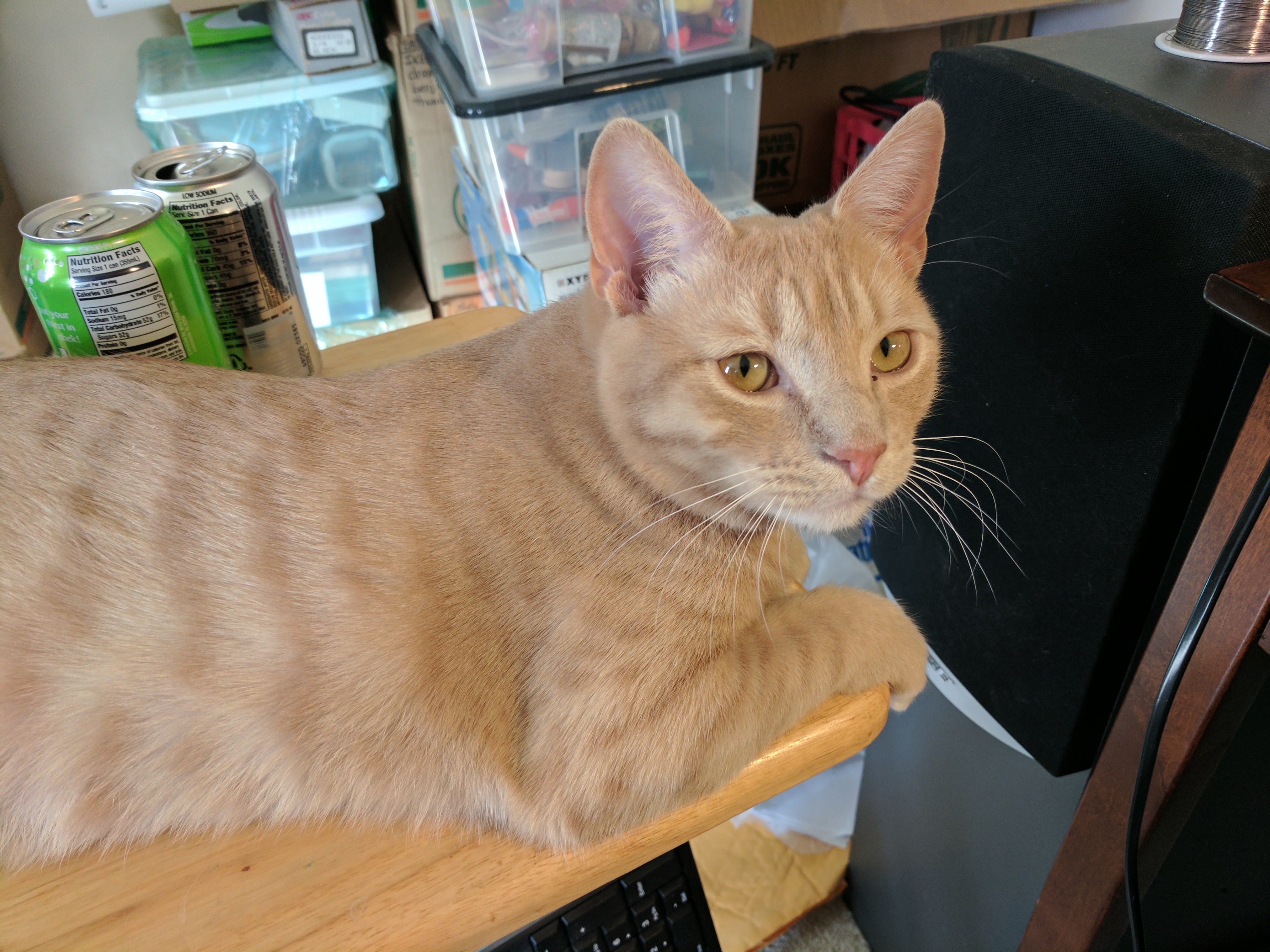
While I was working on the soldering issues, my trusty assistant came to join
me and offer his advice.
After about 30 minutes of reworking the LCD panel header, I retested. There
didn’t seem to be any issues, so I plugged it all back in. Still no luck. I
had a white screen.
I decided to rework the female headers on the main board because I had seen
examples of other people’s soldering work and mine looked very bad in
comparison. Apparently, I was using too much solder. I also didn’t hold the
iron on the pins long enough to let the solder flow to the pads and stick to
the pins.
So, one-by-one, I held the iron to each pin for three seconds. I used the
solder sucker to remove excess solder and added solder where necessary. The
joints looked much better when I was finished.
When I plugged it in, I was happy to be greeted by the boot up message.
However, it still wasn’t right. Remember those bad resistors I told you about
earlier? Well, they manage the voltage level of the incoming signal. Since I
wasn’t sure which resistor was which (they were both very small and had five
bands each. I couldn’t tell what was what and my meter wouldn’t give me a
reading on them).
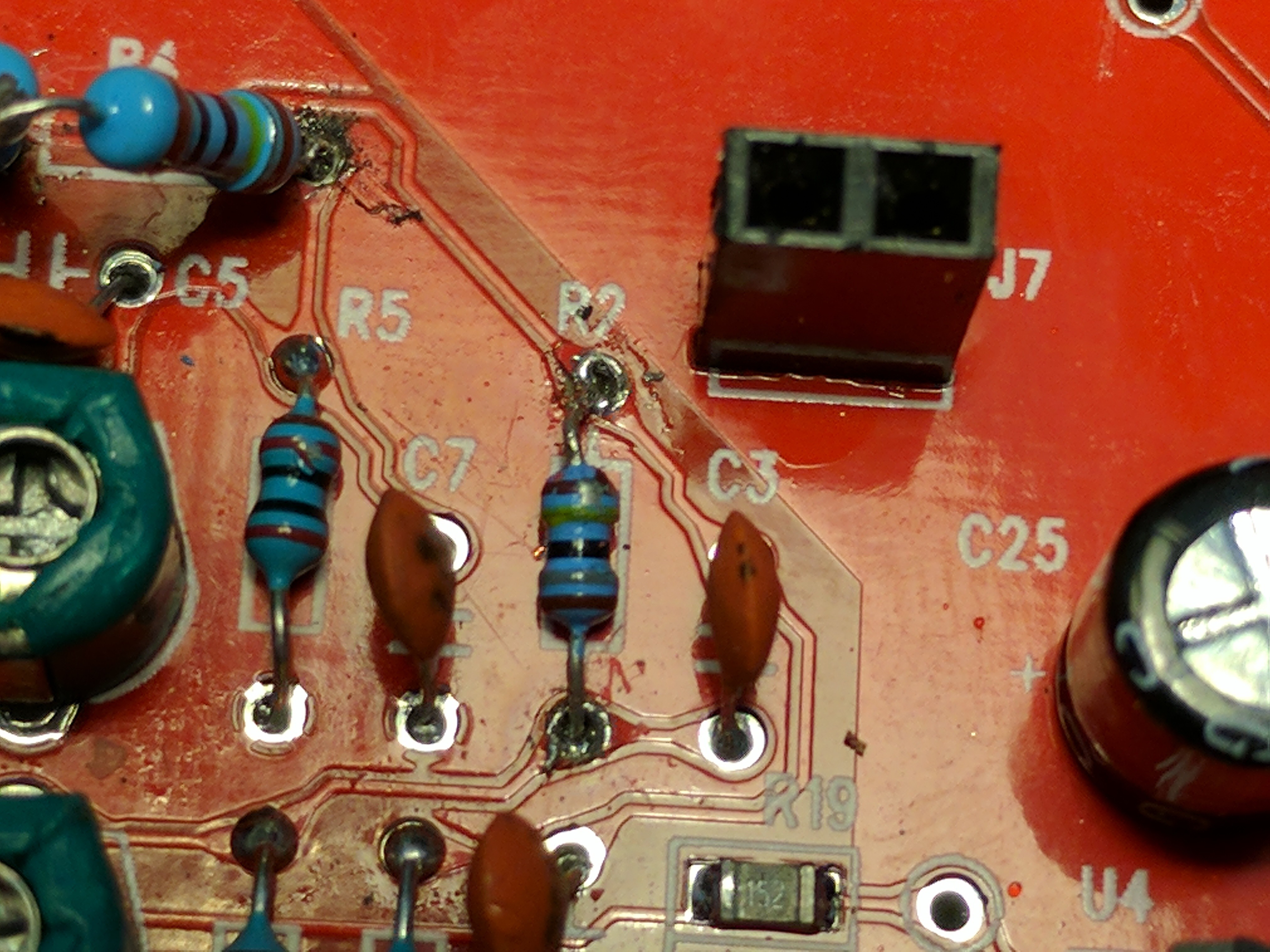
Here is a picture of the horrible looking 1.8MΩ resistor (R2). I destroyed the
board around it when I swapped the two resistors (R2 and R4) late last night
thinking that would help. I just made a bigger mess.
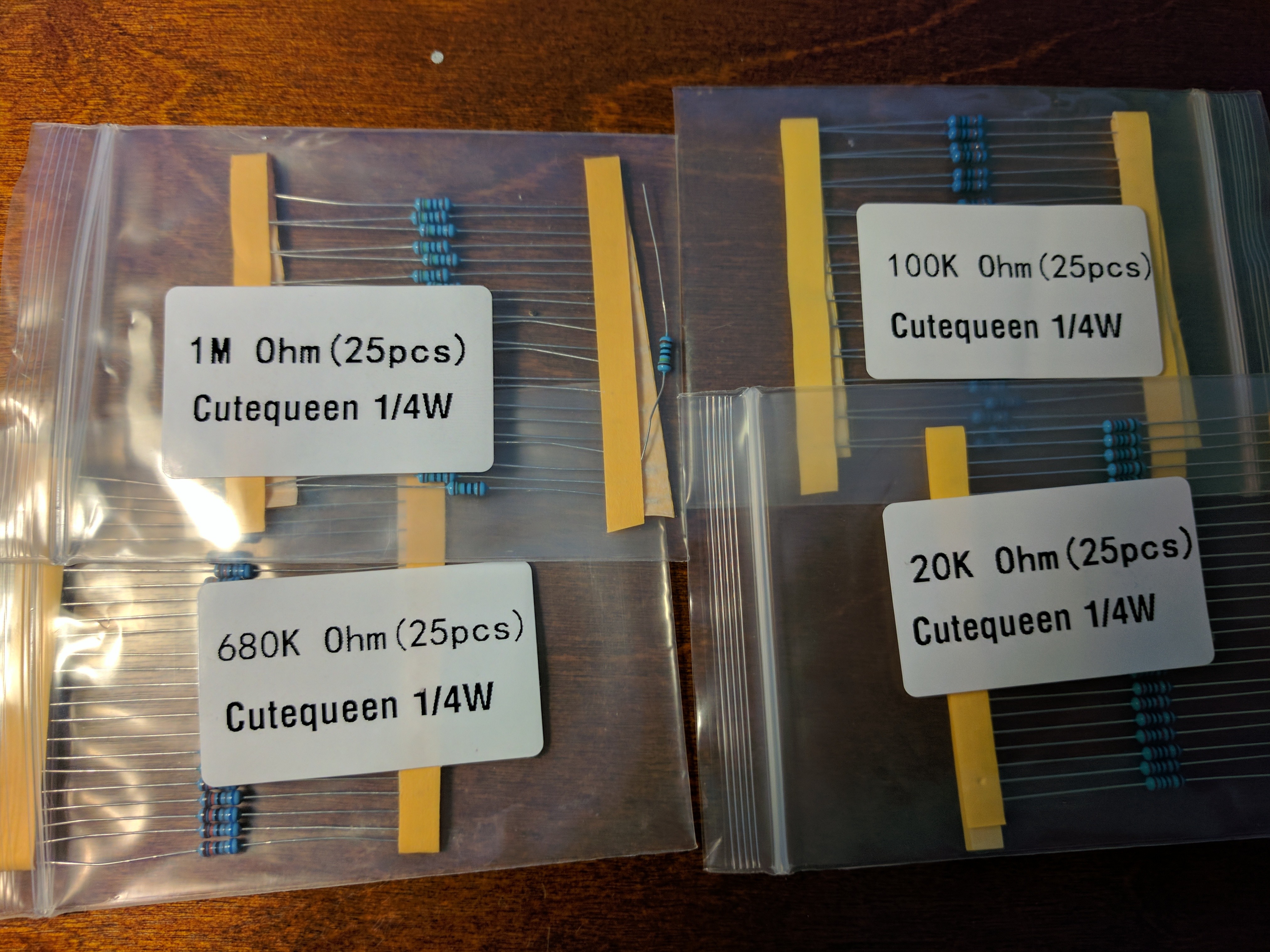
I ended up making my own 2MΩ and 1.8MΩ resistors by putting resistors in
serial. The 2MΩ was easy, I just took two of my 1MΩ resistors, put them in
series, and soldered them in the place of the bad resistor.
When it came time to “make” a 1.8MΩ resistor, I ended up using four values:
- 1MΩ
- 680kΩ
- 100kΩ
- 20kΩ
It’s a definite hack, but my resistor measured correctly (it was actually
closer to the desired value even accounting for the tolerances – I was using
1% tolerance components).
Here are a few pictures of my 1.8MΩ resistor hack…
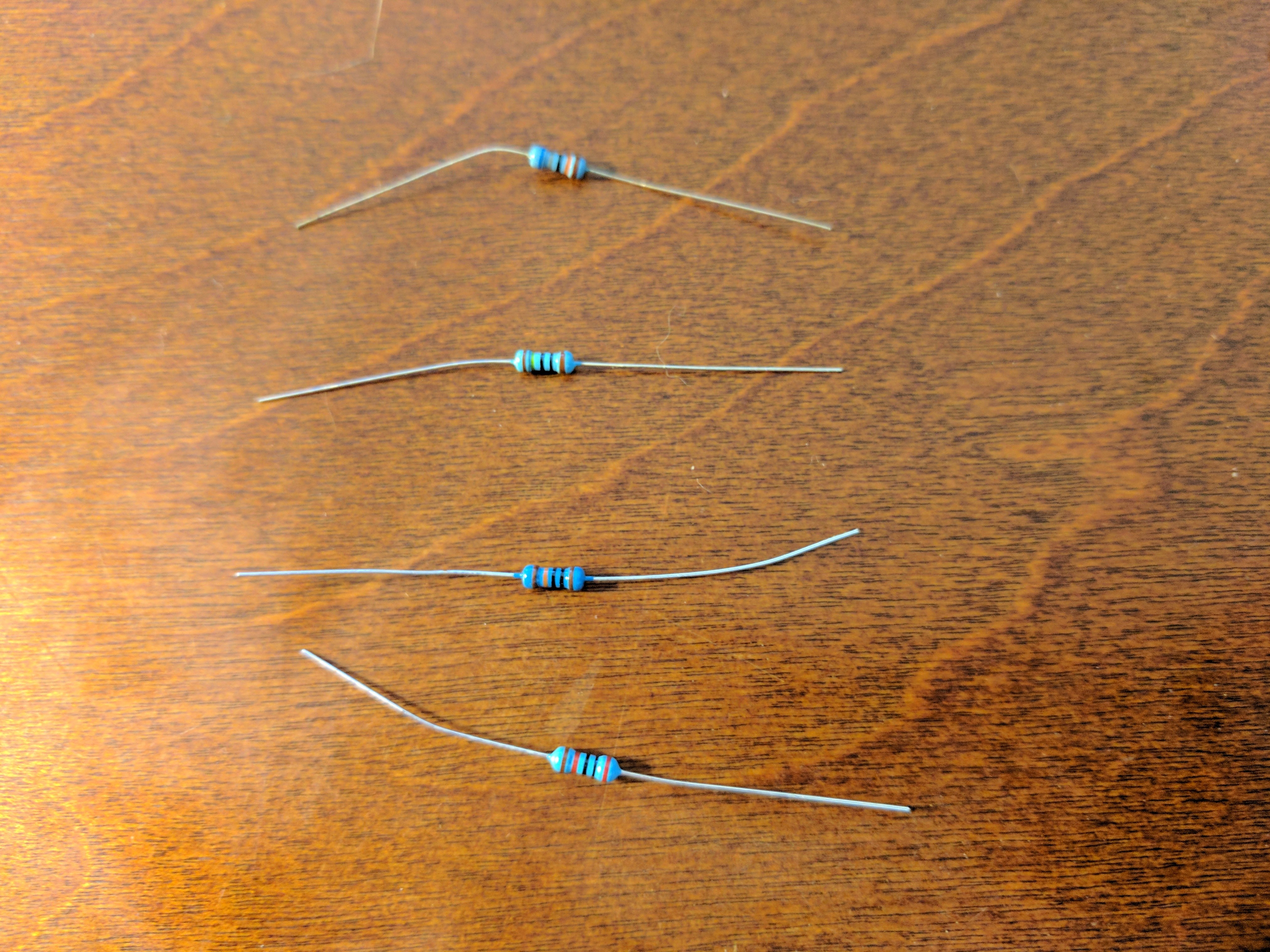
Resistor values
Four resistors assemble!
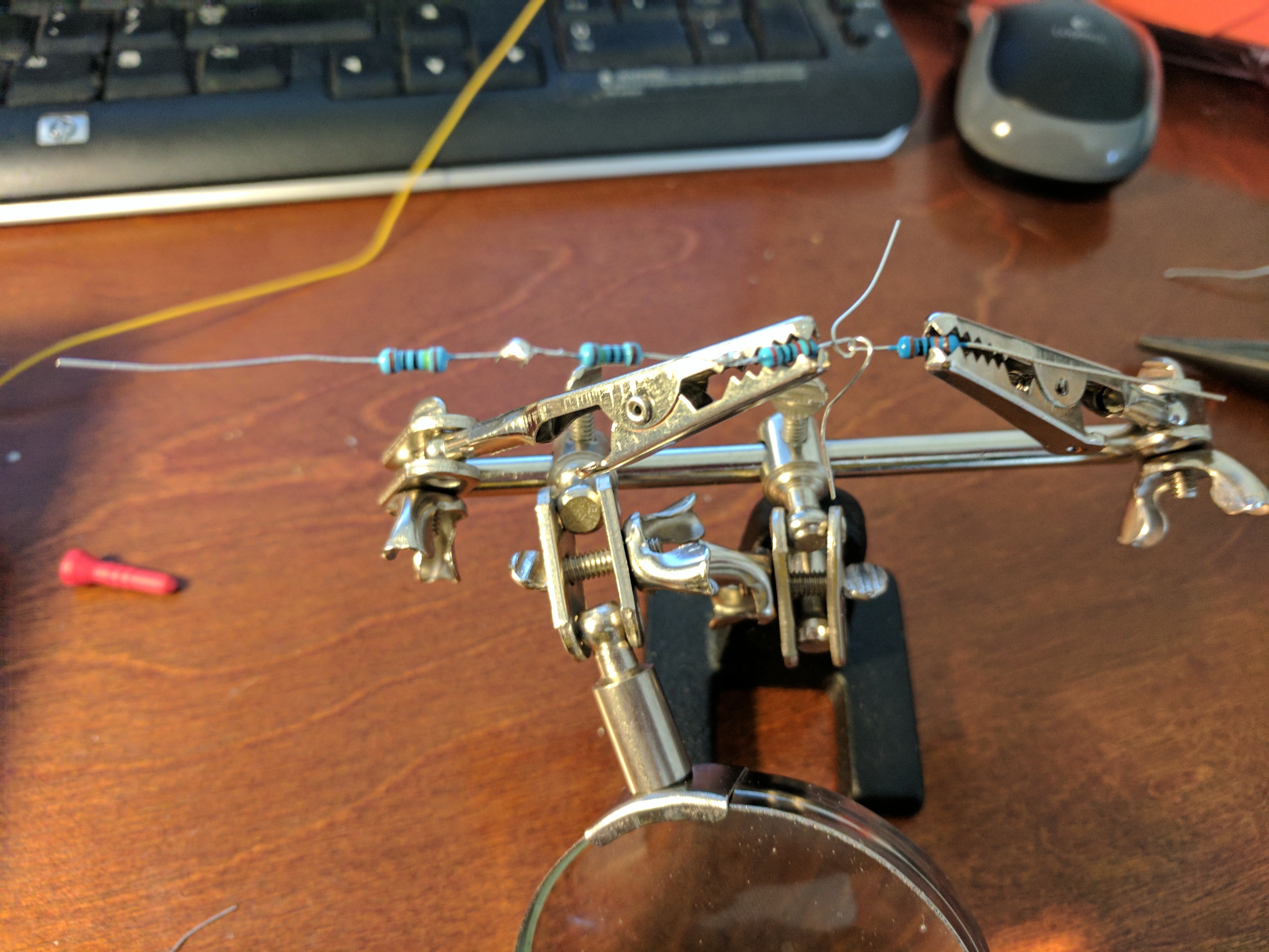
Soldering the resistors in a series
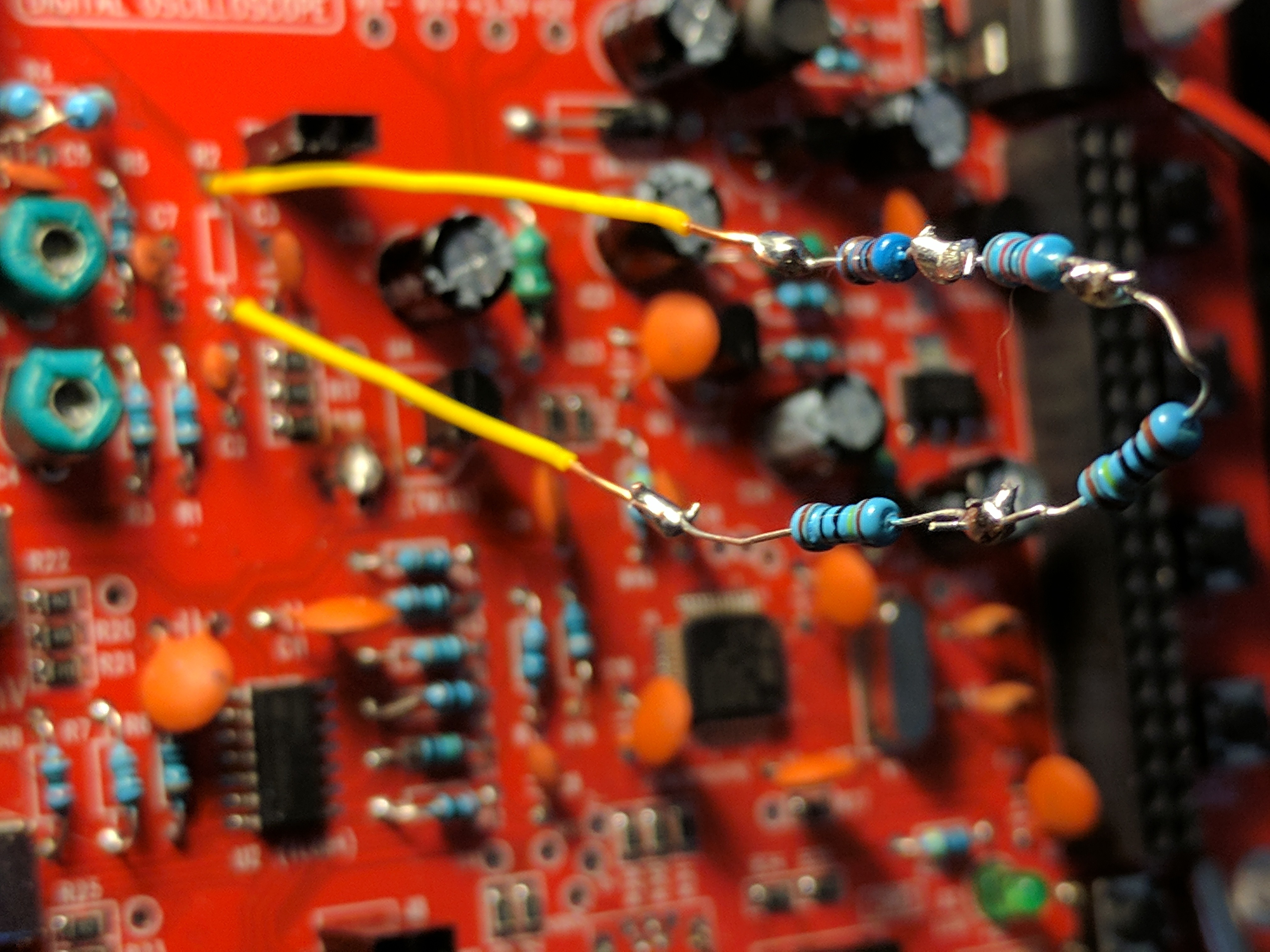
The finished monster
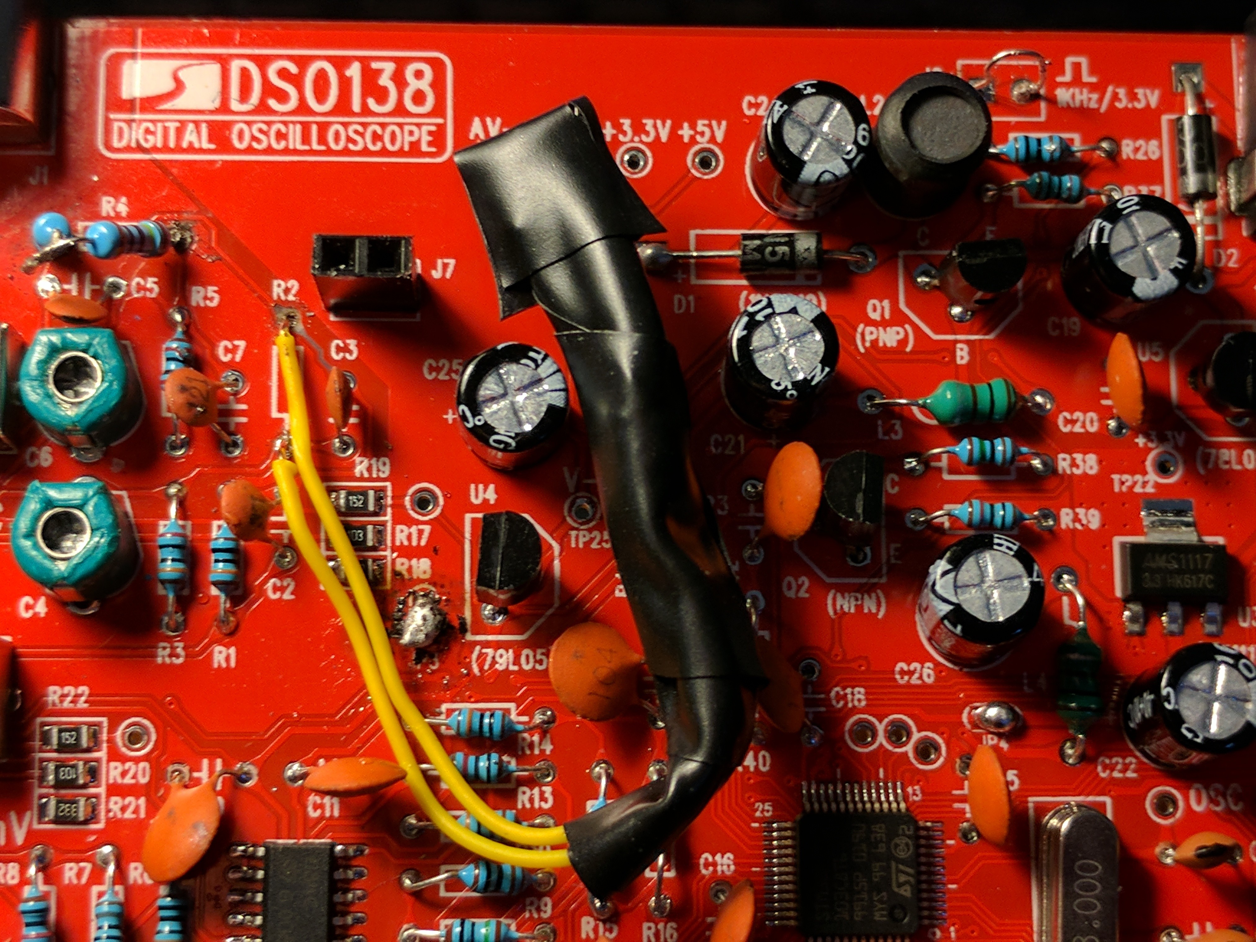
Covering the whole assembly with electrical tape and doing some basic wire
management. If you look at the top left of the picture, you can see my 2MΩ
replacement (R4).
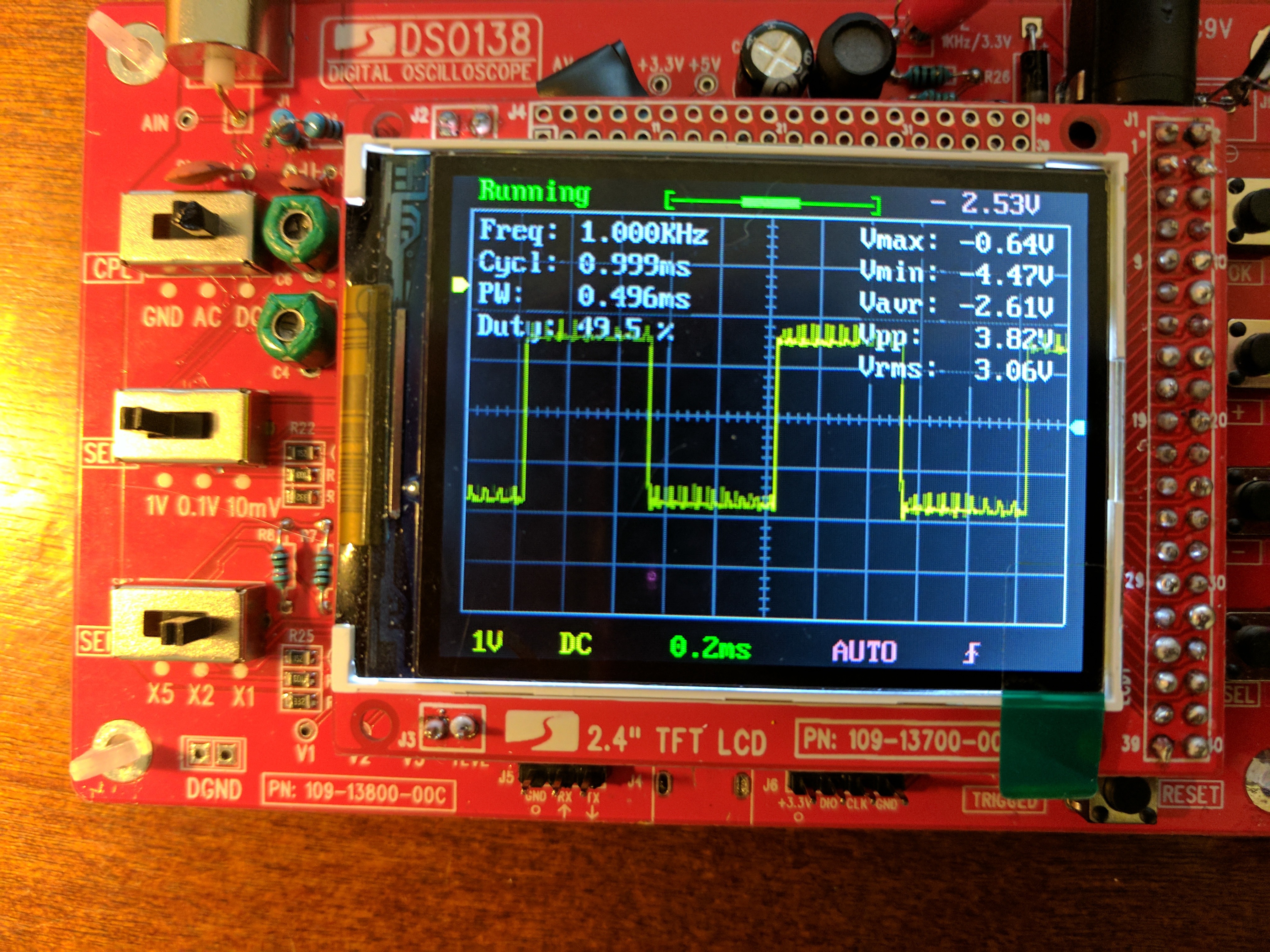
It took me a while to get a useful signal, but when I did, I was excited to
finally get to see it.
This oscilloscope does not have a very impressive range, but it’s just for
hobbyists and learners. It taught me a lot about circuit design, component
placement, and soldering skills.
I’m going to use it to monitor the signals coming from my synthesizer
experiments. Some of the LFOs have frequencies that can’t be heard, so it
would be nice to have a scope to see if they’re working the way I want them
to. Plus, it’s another technical display on my desk. 🙂