Building a Left-Handed Piano MIDI “Man-in-the-Middle” Device

Have you ever wondered what it would be like to play the piano mirrored? What if the low notes were on your right hand and the high melodies were on your left?
I recently built a hardware-based MIDI “Man-in-the-Middle” (MITM) device that does exactly this: it inverts MIDI notes in real-time, allowing you to play any standard MIDI controller as a “Left-Handed” piano. In this post, I’ll break down how this project works, the technical details, and how you can build one yourself!
The Concept: Inverting the Keyboard
The theory behind a left-handed piano is to flip the keyboard layout around a central pivot point. For this project, I chose D4 (MIDI Note 62) as the pivot.
By applying a simple mathematical formula, we can invert the incoming notes:
Inverted Note = 124 - Original Note
With this formula:
- D4 (62) remains D4 (62)
- C4 (60) becomes E4 (64)
- A0 (21) becomes G8 (103)
This creates a perfect mirror image of the keyboard!
The Hardware: Arduino as a MIDI MITM
To achieve this without noticeable latency, I used an Arduino MEGA 2560 to sit horizontally between the MIDI controller and the sound module (or DAW). The MEGA is great for this because it features multiple hardware serial ports (Serial1, Serial2, etc.), allowing high-speed, reliable MIDI handling while still being able to output debug information over USB (Serial).
The flow looks like this:
- MIDI IN: The controller sends Note On/Off messages to the Arduino’s
Serial1. - Processing: The Arduino runs a robust state machine to parse the incoming MIDI bytes. It applies our inversion formula to note data while letting other messages (like Clock or CC) pass through untouched.
- MIDI OUT: The modified MIDI data is sent out to the synthesizer via
Serial2.
Overcoming Technical Hurdles
It might sound simple to just subtract the note number, but MIDI is a serial protocol with some quirks that make real-time processing tricky. Here are a few things the code has to handle gracefully:
1. Zero-Latency Parsing
The code uses a non-blocking state-machine-based parser to process MIDI bytes exactly as they arrive. This ensures there’s no perceptible processing delay when playing fast passages.
2. State Management for “Stuck Notes”
What happens if you press a key, the translation logic changes (e.g., a hardware bypass switch is flipped), and then you release the key? If we inverted the release message based on the current state rather than the state when the key was pressed, we might send a Note Off for the wrong key, resulting in the dreaded “stuck note.”
To solve this, the software maintains an internal array activeNotes[128] to track the exact inverted note that was triggered for every physical key. When a key is released, it looks up the specific note in the array to turn off.
3. MIDI Running Status
MIDI devices often use “Running Status” to save bandwidth. If multiple Note On messages are sent in a row, the status byte (0x90) is omitted for subsequent notes. The parser has to keep track of the last seen status byte to correctly interpret incoming data bytes.
Bill of Materials (BOM)
To build this project, you will need the following components:
- Arduino MEGA 2560: The core processor board providing ample hardware serial ports.
- MIDI Breakout Shield: A board with 5-pin DIN connectors and an optoisolator circuit.
- 4x Jumper Wires: For connecting the shield to the MEGA’s alternate hardware serial pins.
- USB Cable (A-to-B): To power the device and monitor the real-time serial output.
- 2x Standard MIDI Cables: For connecting your keyboard and your synthesizer/audio interface.
Wiring Diagram
Because we want to reserve the MEGA’s primary serial port (Pin 0/1) for PC debugging, we do not simply stack the MIDI shield on top. Instead, we use jumper wires to route the MIDI data to Serial1 (RX1) and Serial2 (TX2).
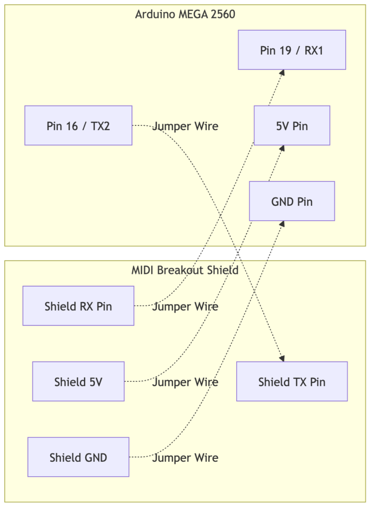
Note: The shield’s RX pin receives data from the MIDI IN optoisolator and connects to the Arduino’s RX1. The Arduino’s TX2 pin sends data to the shield’s TX pin to be transmitted via the MIDI OUT jack.
The Code
Here is a snippet showing the core logic of the full message handler, demonstrating how the note inversion, state management, and serial debugging are applied. This version leverages the robust hardware serial processing available on the Arduino MEGA 2560:
void handleFullMessage() {
  uint8_t status = midiMsg[0];
  uint8_t type = status & 0xF0;
  uint8_t channel = status & 0x0F;
  uint8_t data1 = midiMsg[1];
  uint8_t data2 = midiMsg[2];

  // Active Logic: Invert Note On/Off
  if (type == 0x90 || type == 0x80) {
    uint8_t originalNote = data1;
    uint8_t velocity = data2;

    // Inversion formula: 124 - original_note
    int invertedNote = INVERSION_OFFSET - (int)originalNote;
    if (invertedNote < 0)
      invertedNote = 0;
    if (invertedNote > 127)
      invertedNote = 127;

    if (type == 0x90 && velocity > 0) {
      // Note On
      activeNotes[originalNote] = (int8_t)invertedNote;
      Serial2.write(0x90 | channel);
      Serial2.write((uint8_t)invertedNote);
      Serial2.write(velocity);

      Serial.print("Note On: ");
      Serial.print(originalNote);
      Serial.print(" -> ");
      Serial.println(invertedNote);
    } else {
      // Note Off (type 0x80 or 0x90 with velocity 0)
      int8_t noteToSend = activeNotes[originalNote];
      if (noteToSend == -1) {
        // Failure case: received Note Off without Note On.
        // Just invert it and send anyway to be safe.
        noteToSend = (int8_t)invertedNote;
      }

      Serial2.write(type | channel);
      Serial2.write((uint8_t)noteToSend);
      Serial2.write(velocity);

      activeNotes[originalNote] = -1;

      Serial.print("Note Off: ");
      Serial.print(originalNote);
      Serial.print(" -> ");
      Serial.println((uint8_t)noteToSend);
    }
  } else {
    // Pass through CC and other multi-byte messages
    for (int i = 0; i < expectedBytes; i++) {
      Serial2.write(midiMsg[i]);
    }
  }
}
Conclusion
Building a custom hardware MIDI processor is deeply satisfying and opens up a ton of creative possibilities. By putting a simple Arduino between your keyboard and your synth, you can fundamentally alter how you interact with your instrument.
If you’re interested in giving this a try, grab an Arduino, a couple of MIDI jacks, and start flipping those notes! Happy playing!
