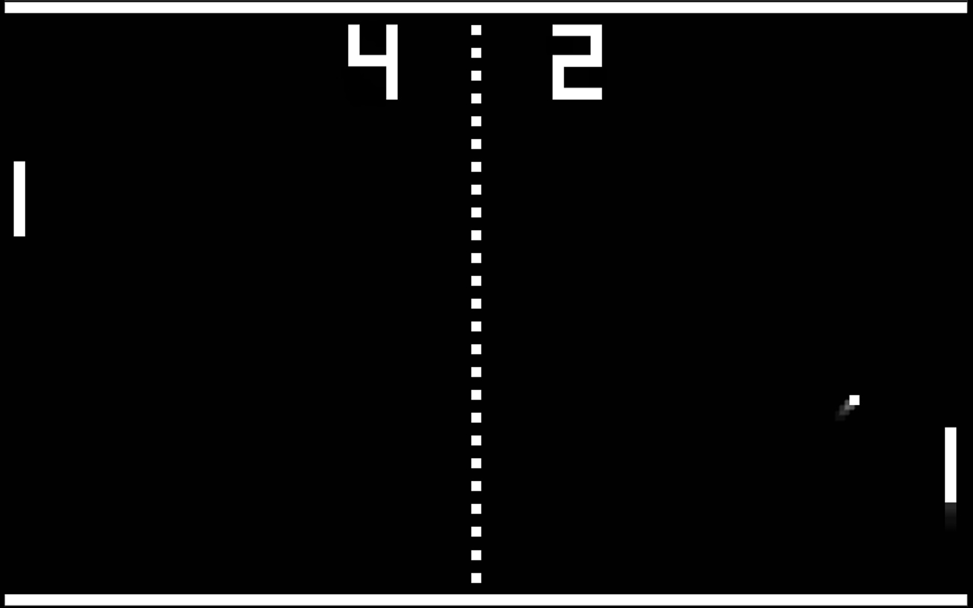
In my [previous post](https://cerkit.com/2017/05/26/creating-pong-on-the-mojo- fpga/), I briefly discussed the implementation of a pseudo-pong game on my Mojo FPGA developer board.
I was able to implement the VHDL version that I linked to later in the post and it works much better.
The biggest challenge I had with it was converting the two-button input to a potentiometer input. It turns out all I had to do was convert an array to an integer as input to the paddle’s left position.
Here is a link to the article describing the implementation that I used:
FPGA Pong From FPGACenter.com.
The VHDL was a big challenge for me because I had to learn it as I went along. It works just like Verilog, but the syntax is so different.
Also, I modified my User Constraints File to make the RGB an array for compatibility with this particular implementation.
Here are the new custom constraints:
NET "hsync" LOC = P50 | IOSTANDARD = LVTTL;
NET "vsync" LOC = P51 | IOSTANDARD = LVTTL;
NET "rgb<2>" LOC = P41 | IOSTANDARD = LVTTL;
NET "rgb<1>" LOC = P40 | IOSTANDARD = LVTTL;
NET "rgb<0>" LOC = P35 | IOSTANDARD = LVTTL;
Here is the code containing my changes (in the vga_control and img_gen
modules):
vga_control:
library IEEE;
use IEEE.STD_LOGIC_1164.ALL;
use IEEE.STD_LOGIC_UNSIGNED.ALL;

entity vga_control is
     Port ( clk : in STD_LOGIC;
                start : in STD_LOGIC;
                reset : in STD_LOGIC;
                paddle : IN STD_LOGIC_VECTOR(9 downto 0);
                rgb : out STD_LOGIC_VECTOR (2 downto 0);
                h_s : out STD_LOGIC;
                v_s : out STD_LOGIC);
end vga_control;

architecture Behavioral of vga_control is

COMPONENT img_gen
       PORT( clk : IN std_logic;
                     x_control : IN std_logic_vector(9 downto 0);
                     paddle : IN std_logic_vector(9 downto 0);
                     y_control : IN std_logic_vector(9 downto 0);
                     video_on : IN std_logic;
                     rgb : OUT std_logic_vector(2 downto 0) );
END COMPONENT;

COMPONENT sync_mod
       PORT( clk : IN std_logic;
                     reset : IN std_logic;
                     start : IN std_logic;
                     y_control : OUT std_logic_vector(9 downto 0);
                     x_control : OUT std_logic_vector(9 downto 0);
                     h_s : OUT std_logic;
                     v_s : OUT std_logic;
                     video_on : OUT std_logic );
END COMPONENT;

signal x,y:std_logic_vector(9 downto 0);
signal video:std_logic;

begin
          U1: img_gen PORT MAP( clk =>clk , x_control => x, paddle => paddle ,
                                                         y_control => y, video_on =>video , rgb => rgb );

           U2: sync_mod PORT MAP( clk => clk, reset => reset, start => start, y_control => y, x_control =>x ,
                                                             h_s => h_s , v_s => v_s, video_on =>video );
end Behavioral;
My changes are on lines 9, 20, and 41. This sends the output from the potentiometer hooked up to the ADC on the Mojo to the img_gen module where it’s converted to position data for the paddle control.
Here’s the modified img_gen code:
library IEEE;
use IEEE.STD_LOGIC_1164.ALL;
use IEEE.STD_LOGIC_ARITH.ALL;
use IEEE.STD_LOGIC_UNSIGNED.ALL;


entity img_gen is
     Port ( clk : in STD_LOGIC;
                x_control : in STD_LOGIC_VECTOR(9 downto 0);
                paddle : in STD_LOGIC_VECTOR(9 downto 0);
                y_control : in STD_LOGIC_VECTOR(9 downto 0);
                video_on : in STD_LOGIC;
                rgb : out STD_LOGIC_VECTOR(2 downto 0));
end img_gen;

architecture Behavioral of img_gen is

--wall
constant wall_l:integer :=10;--the distance between wall and left side of screen
constant wall_t:integer :=10;--the distance between wall and top side of screen
constant wall_k:integer :=10;--wall thickness
signal wall_on:std_logic;
signal rgb_wall:std_logic_vector(2 downto 0);

--bar
signal bar_l, bar_l_next: integer:=100;
constant bar_t:integer :=420;--the distance between bar and top side of screen
constant bar_k:integer :=10;--bar thickness
constant bar_w:integer:=120;--bar width
constant bar_v:integer:=10;--velocity of the bar
signal bar_on:std_logic;
signal rgb_bar:std_logic_vector(2 downto 0);

--ball
signal ball_l,ball_l_next:integer :=100;--the distance between ball and left side of screen
signal ball_t,ball_t_next:integer :=100; --the distance between ball and top side of screen
constant ball_w:integer :=20;--ball Height
constant ball_u:integer :=20;--ball width
constant x_v,y_v:integer:=3;-- horizontal and vertical speeds of the ball
signal ball_on:std_logic;
signal rgb_ball:std_logic_vector(2 downto 0);

--refreshing(1/60)
signal refresh_reg,refresh_next:integer;
constant refresh_constant:integer:=830000;
signal refresh_tick:std_logic;

--ball animation
signal xv_reg,xv_next:integer:=3;--variable of the horizontal speed
signal yv_reg,yv_next:integer:=3;--variable of the vertical speed

--x,y pixel cursor
signal x,y:integer range 0 to 650;

--mux
signal vdbt:std_logic_vector(3 downto 0);

--buffer
signal rgb_reg,rgb_next:std_logic_vector(2 downto 0);

begin

--x,y pixel cursor
x <=conv_integer(x_control); y="" <="conv_integer(y_control" );="" --refreshing="" process(clk)="" begin="" if="" clk'event="" and="" clk="1" then="" refresh_reg<="refresh_next;" end="" if;="" process;="" refresh_next<="0" when="" refresh_reg="refresh_constant" else="" refresh_reg+1;="" refresh_tick<="1" '0';="" --register="" part="" ball_l<="ball_l_next;" ball_t<="ball_t_next;" xv_reg<="xv_next;" yv_reg<="yv_next;" bar_l<="bar_l_next;" --bar="" animation="" process(refresh_tick,paddle)="" refresh_tick="1" bar_l_next<="conv_integer(paddle);" --ball="" process(refresh_tick,ball_l,ball_t,xv_reg,yv_reg)="" ball_l_next="" ball_t_next="" xv_next<="xv_reg;" yv_next<="yv_reg;" ball_t=""> 400 and ball_l > (bar_l -ball_u) and ball_l < (bar_l +120) then --the ball hits the bar
           yv_next<= 10="" 35="" -y_v="" ;="" elsif="" ball_t<="" then--the="" ball="" hits="" the="" wall="" yv_next<="y_v;" end="" if;="" if="" ball_l="" <="" then="" --the="" left="" side="" of="" screen="" xv_next<="x_v;"> 600 then
          xv_next<= -x_v="" ;="" --the="" ball="" hits="" the="" right="" side="" of="" screen="" end="" if;="" ball_l_next="" <="ball_l" +xv_reg;="" ball_t_next="" process;="" --wall="" object="" wall_on="" when="" x=""> wall_l and x < (640-wall_l) and y> wall_t and y < (wall_t+ wall_k) else
                      '0';
rgb_wall<="000";--black --bar="" object="" bar_on="" <="1" when="" x=""> bar_l and x < (bar_l+bar_w) and y> bar_t and y < (bar_t+ bar_k) else
                    '0';
rgb_bar<="001";--blue --ball="" object="" ball_on="" <="1" when="" x=""> ball_l and x < (ball_l+ball_u) and y> ball_t and y < (ball_t+ ball_w) else
                     '0';
rgb_ball<="010"; --green="" --buffer="" process(clk)="" begin="" if="" clk'event="" and="" clk="1" then="" rgb_reg<="rgb_next;" end="" if;="" process;="" --mux="" vdbt<="video_on" &="" wall_on="" bar_on="" &ball;_on;="" with="" vdbt="" select="" rgb_next="" <="100" when="" "1000",--background="" of="" the="" screen="" is="" red="" rgb_wall="" "1100",="" "1101",="" rgb_bar="" "1010",="" "1011",="" rgb_ball="" "1001",="" "000"="" others;="" --output="" rgb<="rgb_reg;" behavioral;<="" code="">
My changes are on lines 10 and 95 to make the potentiometer control the paddle.